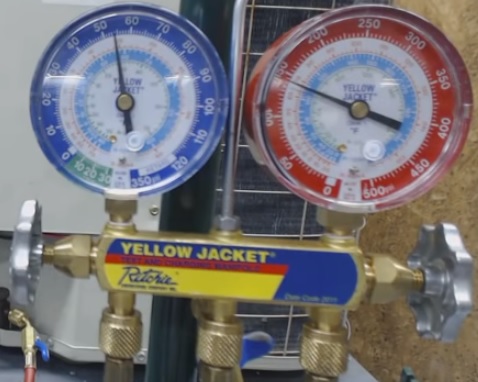
HVAC gauges are a very important part of troubleshooting, fixing, and repairing heating and cooling systems.
Understanding how they work is one of the more crucial things a technician will need to know.
Below is a basic overview of how HVAC manifold gauges work, along with pictures.
What are HVAC Gauges?
HVAC gauges are a tool for refrigeration HVAC technicians to take pressure readings and other tasks.
Tasks include vacuuming, testing, adding refrigerant, and recovery.
A set will have high-pressure and low-pressure sides and on/off valves that a technician can use to perform various operations.
Components of an HVAC Gauge
An HVAC manifold set has two gauges, blue and red.
The blue is for low pressures, and the red is for high pressures.
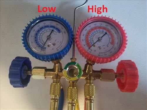
The red and blue valves on the side turn on and off to control refrigerant going to the low and high-pressure valves.
A manifold gauge set will have red, blue, and yellow hoses.
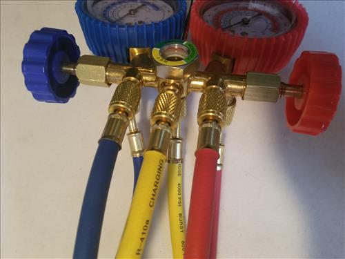
- The blue hose goes to the low pressure gauge.
- The yellow hose can go to either the low side or high side, depending on which valve is open.
- The red hose goes to the high pressure valve.
The center where everything attaches is called the manifold.
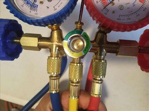
The unit in the picture has a sight glass which is a feature most don’t have.
The hoses will attach to the manifold at the bottom with the top connections only there to keep the hoses clean.
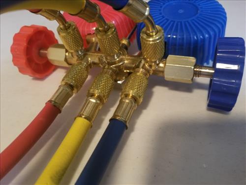
For example, here the bottom is the working part and the top part with the hoses disconnected only keeps the hoses clean.
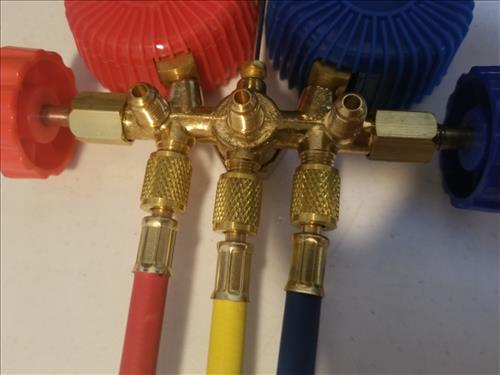
The extra connections that go to nothing also keep the hoses from getting tangled and easy to store away.
How to Use HVAC Gauges
When using the gauges, refrigerant flow through a set needs to be understood.
Here a diagram shows how gas can flow through a manifold.
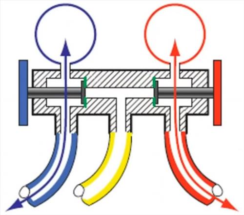
The red and blue hoses go straight to the red and blue gauges, while yellow center hose is separate.
The yellow hose can connect to any external source. For example, a vacuum pump will have the yellow connected to it.
While vacuuming down an HVAC unit, the low-pressure blue hose would go to the unit and the yellow hose to the vacuum pump.
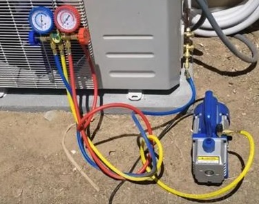
While the pump is working the blue valve will be opened to let the pump work.
In this example, refrigerant is being added to an A/C system.
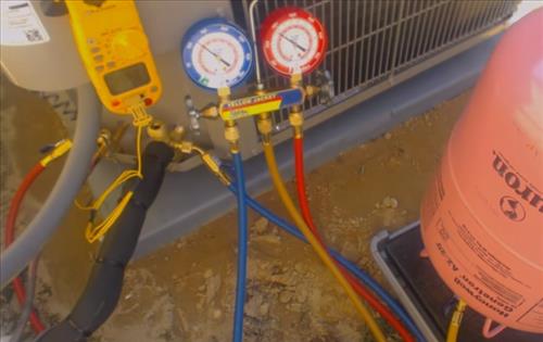
The yellow hose is going to the refrigerant bottle and the red hose is going to the unit.
The red valve will control how much goes into the unit and is turned off when the correct amount has been added.
The gauges can also show the pressures when connected to an HVAC unit.
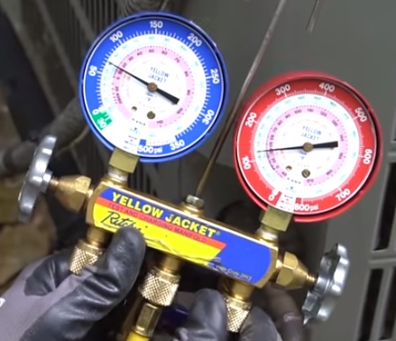
The yellow hose will not be used to get pressure readings.
To get pressure readings, the red hoses attaches to an HVAC system high-pressure line.
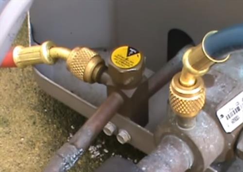
The blue hoses attaches to an HVAC system low-pressure line.
Types of HVAC Manifold Gauges
HVAC manifold gauges must match the refrigerant used in a system to get the correct readings.
Main Types of Refrigerants and Manifold Gauges
- R410A
- R134a
- R22
Every heating and cooling system will have a stamp of what type of refrigerant it uses.
Be sure to use gauges that match the refrigerant type, or any readings will be wrong.
Many gauges can read multiple types of refrigerants, so be sure to know your set’s features.
Summary
The above is a basic overview of HVAC gauges and how they work.
After the gauge manifold workings are understood, more advanced topics such as reading pressures can be learned.
Basic tasks such as vacuuming down a unit can be done with the above basic overview.
HVAC gauges are a simple but very powerful tool for troubleshooting and working any heating and cooling system with refrigerant.
New digital gauges are also available and used by many, but the basic principles will still apply.
This is informative. Thanks for sharing.
I really appreciate your tutorial for information. It was worth watching the videos