- Wiring Mini Split Inside Control Wires
- Wiring a Mini Split Electric AC
- Items Needed Disconnect Box
- Types of Wire Gauge for Mini Split
- Wiring a Disconnect Box To Mini Split
- Wiring from Breaker Panel to the Disconnect Box
Wiring up a mini split HVAC unit is not difficult but does require some basic electrical knowledge.
This post gives a basic overview of wiring up a mini split.
The instructions that come with any unit should always be followed.
There are two types of wiring that will need to be done.
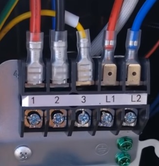
- Electrical AC Power (Usually labeled L1, L2, and Ground)
- Inside Unit Control Wires (Usually labeled 1, 2, 3)
The AC electrical voltage will be 110-120 or 220-230 Volts.
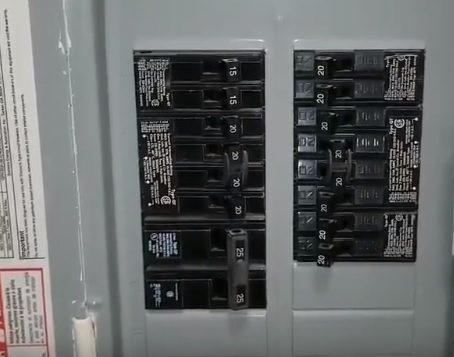
It will be supplied from an electrical panel which will hold all the breakers for a home.
The breaker will need the correct amps the mini split is rated for and will be displayed on the breaker.
For example, a breaker labeled 15 will be a 15 amp breaker, or 20 will be a 20 amp breaker.
Electrical AC wiring will need to be bought separately from DIY mini split kits and is not included.
The control wires go between the inside and outside units.
There are usually 3-5 control wires that are easy to wire up.
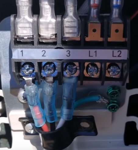
Control wires are included in most any good DIY mini split install package.
Wiring Mini Split Inside Control Wires
- Run the Control Wires
- Match the color of the wires to the labeled numbers
Most Mini Split units will have the inside and outside units marked with numbers 1, 2, 3, and ground which the wires color code will match.
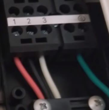
For example, if a red wire is connected to the inside number 1, it will be connected outside to the number labeled 1.
Wiring the control lines is straightforward and easy enough by simply matching wires colors to the labeled numbers.

Most all DIY mini split kits will come with the DC control line wiring.
Wiring a Mini Split Electric AC
- Know the Correct Voltage (110-115/220-230)
- Know the Amps
- Use the Right Breaker Size
- Use the Right Wire Gauge
Wiring the AC electrical needs to be thought out with each situation different.
Mini Split units come in all sizes and have different voltage and amps.
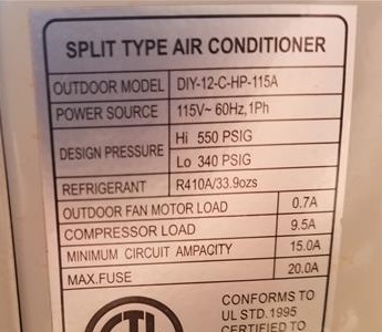
The voltage, as well as amps, will be in the instructions and on the unit itself.
The voltage can be standard 110-115 volts or 220-230 volts.
The amps it draws to run will also be rated.
The unit will need the rated breaker size to run the unit and trip off if there is a problem.
As most know, this is what a breaker does it shuts off, stopping the flow of power if there is a problem.
Items Needed Disconnect Box
Most all mini spits units will need a disconnect box placed close to the unit to turn on and off the power.
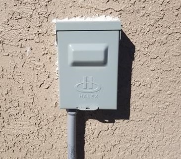
A disconnect box is simply a junction that, like a switch, turns on and off the power when needed.
The disconnect is not a breaker but an emergency shut-off and is used by technicians to shut power off when working on the unit.
Example Disconnect Box on Amazon
SIEMENS WN2060U Non-Fused AC Disconnect
Types of Wire Gauge for Mini Split
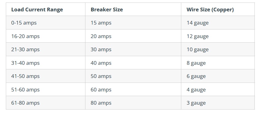
Wire gauge is how thick the wire is with different sizes for different voltages and amps.
| Gauge Size | Amps | Example Uses |
| 16 Gauge | 13 Amps | Extension cords |
| 14 Gauge | 15 Amps | Lamps / Lights / Some Mini Splits |
| 12 Gauge | 20 Amps | Outlets / Some Mini Splits |
| 10 Gauge | 30 Amps | Clothes Dryers / Some Mini Splits |
| 6-8 Gauge | 40-50 Amps | Electric Stoves Furnaces |
| 4 Gauge | 60 Amps | Electric Stoves Furnaces |
The wire gauge needed will be in the instructions, with common sizes for mini split units being 10-12 gauge.
While most units will be 10-12 gauge, be sure to read the specifications to get the correct size wire.
For example, what wire gauge does a 12,000 BTU mini split use?
A 12,000 BTU mini split will most often use 12 gauge wire.
Wiring a Disconnect Box To Mini Split
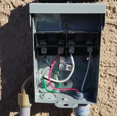
Disconnect Boxes are simple to wire up with power coming in and going out.
The box will have wiring coming from the breaker and going out to the mini split.
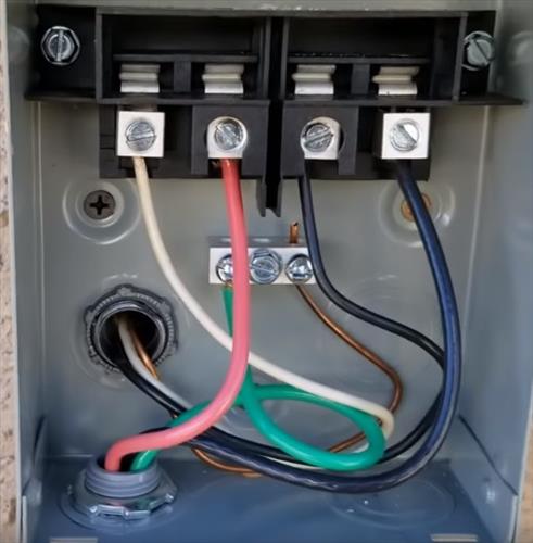
They have a pull-out that turns the power off and on.
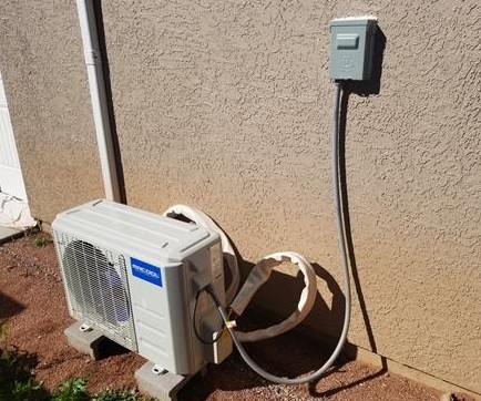
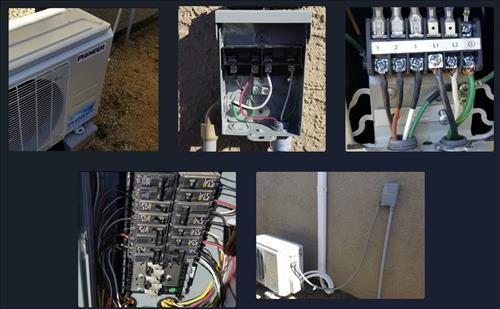
The wires are fed into the outside condensing unit and are usually marked L1 and L2 along with green for ground.

An electrical whip is commonly used to go from the disconnect box to the mini split.
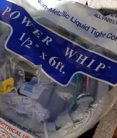
A whip is a prepackaged electrical line that is quick and easy to install.
Electrical wires will need to be run from the breaker to the disconnect box with an electrical whip making it quick and easy to run to the mini split unit.
Example Electrical Whip on Amazon
Sealproof Power Whip Assembly, 1/2-Inch x 6 Ft
Wiring from Breaker Panel to the Disconnect Box
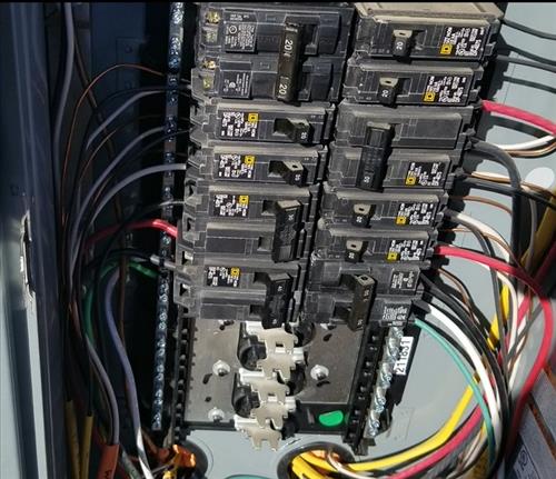
Running the electrical from a breaker panel to the disconnect box can be done many different ways.
The location of the panel and the outside mini split location is always different.
The first step is to know the location the Mini Split will sit at.
The next step is to find the electrical panel which holds the breakers.
Most HVAC companies will install a breaker with the correct amps and run a new line to the disconnect.
The right wire gauge and length will need to be bought.
For example, a 20-foot run will need enough wire to go the entire distance.
Conduit for the wire will also be needed with three main types, Liquid Tight, Metal Conduit, and PVC.
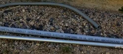
Each type works well and is often a personal preference on which to use.
When I install a unit, I almost always use liquid-tight and PVC, with both very flexible and easy to use.
The main goal of the conduit is to protect the wire from the elements.
Most of the time, the conduit is run along a wall but can be buried or run through the walls of some homes.
Whichever conduit is used, for a mini split most all are sized 1/2-Inch.
Liquid Tight Conduit on Amazon
Sealproof 1/2-Inch Flexible Nonmetallic Liquid-Tight Electrical Conduit Type B, UL Listed, 1/2″ Dia, 25 Feet
Wiring the breaker is like any other appliance and will depend on whether the unit is 115 or 220 volts.
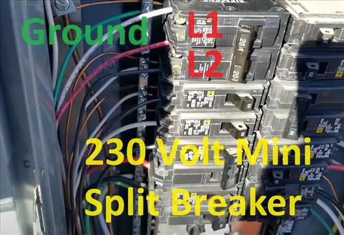
Below is a full video for wiring a mini split electrical to a panel along with connecting to a disconnect and breaker.
Summary
Wiring up a mini split unit is not difficult if you have some wiring experience, such as hooking up a ceiling fan or electric water heater.
If in doubt, be sure to call a professional.
Each wiring scenario from the breaker to the disconnect will be different.
Sometimes a home’s existing wiring can be tapped into and used depending on the scenario.
The wiring from the disconnect to the outside condensing unit is almost always the same.
This post is meant to give the basics of wiring up a mini split.
With the many mini split air conditioner heat pump available, there is likely to be variations.
Be sure to always follow the instructions that come with your unit.
Most mini split systems on the market feed the line voltage directly back to the air handler through terminals 1 and 2, so they are usually not “DC control wires” like this writer says. #3 is the singular control wire.
I have a pioneer 1800btu mini split it calls for a 20amp breaker do I need a single or double breaker? And if the double breaker is required how do I wire a double breaker with 12/2
I thank you for the good help my god bless you
My mini split says Maximum Over Current Protection 25A so will i need a 25amp breaker instead of a 20amp breaker?
I have no power from
L1 and L2 L1 to ground 110 L2 to ground 110 nothing on L1 and L2 were is my mistake??
No difference of potential therefore “0” volts
L1 and L2 are connected to the same polarity of a single phase service.
If the compressor is made for 120v power, L1 is the ungrounded (black) power conductor and L2 is the (white) grounded (neutral) power conductor. (Not the same as the (green or bare) grounding conductor because it carries current in routine is. If the conductor breaks or a splice fails it may be at line potential.)
If the compressor is made for 240v power, then the same polarity has been connected to both L1 and L2.
In a single phase 240v load center the 120v polarity reverses between adjacent stabs so that a double pole circuit breaker is 240v line to line. Its common practice for 240v branch circuit to use black wire for one of the ungrounded power polarities and red wire for the other, but the only requirement is that they can’t be white or green. If the branch circuit serves a 240v load there is no requirement to cable a neutral along just to cap it, but its the smart thing to do in case some replacement down the line does need it. If 2 conductor + ground cable is used, 3 wire cable is rarely found other than black+white+gnd and using white for an ungrounded conductor is prohibited. When it’s used an an ungrounded conductor the white insulation must be taped to make it unambiguously any color other than white or green. For some reason (that amounts to convenience) the same rule wasn’t applied to wiring a switches to interrupt power to a load.
In a single phase 120v load center all the stabs are the same polarity and a double pole breaker is 0v line to line. If a double pole breaker was installed for a 240v load because someone simply assumed it was a 240v load center then the only way to get 240v is to get 240v to the load center. If the service is 120v the service entrance would have to be upgraded. Some load centers away from the service entrance have been downgraded to 120v to comply with a change to the electrical code change that separated the grounded and grounding conductors at load centers away from the service entrance. It was once possible to cable them using low cost aluminum SE cable which has 2 power conductors and a grounded conductor. If the wiring is renovated or the load center is replaced, and if it only serves 120v loads it can rewired as a 120v load center to avoid pulling a new wire from the service entrance. If it now has to supply a 240v load the cable will have to be pulled.
Thanks for this information!
I have a shut off box for my hot tub next to my condensor on a 55 amp breaker. can I use that power source for my 12000 230 volt mini split
Did you get a answer for that cause I would like to do that as well…thanks
So I was dumb enough to wire up 240v to a 120v, I know I burned up the mother board. Did I possibly ruin any other parts of the unit? Any advice is much appreciated
recently had my roof re-done and they disconnected the wires from the unit on roof to the breaker box they connected the white neutral back to the correct slot on the breaker box but connected the black hot wire to the ground and know my unit won’t turn on I disconnected the hot wire from the ground and connected to the correct
slot but still unit won’t turn on did they fry the unit
Do I need a disconnect for a 12k mini split 120v? If so where can i buy one, all the boxes and whips are for 240v
A 240 volt disconnect will work with 120 volts
I’m pretty sure I messed up. At first I ran a 12/2 wire from the breaker box to the condensing unit and I was told to use a 10/2 instead. Is this okay? It sucks because I already buried the line in conduit. I have a Mr Cool DIY Mini Split 18,000.
The wire depends on the AMP the units requires. A 12/2 is perfectly fine for a 15amps, even a 14/2 would do.
Here is the chart for Montreal, Canada.
Nº 6 : 60 ampères, 240 volts,
Nº 8 : 40 ampères, 240 volts,
Nº 10 : 30 ampères, 240 volts,
Nº 12 : 20 ampères, 240 volts
Nº 12 : 20 ampères, 120 volts,
Nº 14 : 15 ampères, 120 volts
That said, I’ve seen 12/2 wire on 30AMPS breaker in old houses and nothing bad happened; the new standards are just very very conservative.
18,000 BTU only calls for 12/2 wire. It seems only when you jump up to 24,000 BTU you need 10/2 wire.
What size wire you require to connect from the panel to the disconnect for a 24,0000btu mini splic ac? And what size breaker will it need
hey I bought a delta 18000 mini split heating and cooling pump I’m putting outside a building which is wired from my house with a separate breaker box. Do I need a disconnect box for the unit or can I run it straight from the buildings breaker box to the unit if so what size amp and wire do I need if not what size amp/wire “I need for the buildings breaker box the amp and wire to the disconnect box and unit.
I just hooked my unit up and when I powered it up it keeps flashing 88° and a beep goes off but unit won’t run any ideas
You drilled a 3+ inch hole under the inside unit. My installation will have the inside blower mounted on an inside wall, and 8 feet to the left is the outside wall where the outside unit is mounted. can the copper lines be run straight out the inside blower housing along the wall, till it gets to the outside wall hole, and there it gets fed to the outside unit? see drawing below.
x…………………………………….inside blower
outside hole
Yes, but it can become difficult to make the drain function and protect the cables and tubing from nails.
The electrical code requires that the line voltage “signal” wires be protected from nails and you’d want to do the same for the refrigerant lines and the drain line. A wall or partition studded using 2×4 (1.5 x 3.5 after planing) shouldn’t be drilled with a 3” hole saw and a 2×3 (1.5 x 2.5 after planing) stud can’t be, and a 2×6 (1.5 x 5.5) is weakened to a point that requires structural reinforcement. Do not weaken a wall with the intention of shoring it up later. Reinforce a wall before making any changes that would weaken it. Make individual holes for drain line, refrigerant lines, and electrical cable, in that order from bottom to top. On a 2×6 wall smaller holes can be drilled closer to one face and beyond the reach of of nails from the far side so they only need to be protected with steel nail plates on one side. A thinner than 2×6 wall will have to provide protection from both sides. Exterior walls may also have siding nails driven between studs. Protecting the cable and liquid lines would require installing then Inside EMT (thin wall conduit) or another other metal sheath that can deflect or stop a siding nail. Its simpler to install it in short lengths with a coupling between each stud and the couplings are hidden in the wall.
It’s necessary to use a rigid pipe for the drain lateral. If would need to be protected from nails use galvanized steel pipe rather than PVC. The usual corrugated polyethylene (bilge pump) hose isn’t allowed in-wall by any building code and it sags between studs creating a series of traps that each adds more back pressure to the drain causing the pan to overflow and drip into the room. The rigid pipe will have to be installed in short segments with couplings between each stud. At the ends adapt to FPT fittings and use MPT to hose barb to get back to hose for the drain connections. If the installation is a PVC drain pipe, Do not use the more easily found metal MPT to hose barb fittings use pvc if available, or nylon. For PVC use a plastic pipe thread sealer, not Teflon tape. Over time the difference in thermal expansion and hardness will cause metal pipe thread in a pvc socket to loosen and leak. Use plastic thread sealer goop instead of Teflon tape because if the threads are tightened enough for the Teflon to flow and seal the threads the pvc socket will eventually crack and leak. Just put on the goop and tighten until it’s just snug, don’t tighten it like a metal pipe joint.
I bought a Mr. Cool 9000 btu mini split system. The manual shows for the outside unit 9k & 12K “Minimum Cross-Sectional Area of Power and Signal Cables” 15 amp 14 AWG. I have been looking at a lot of information but am not able to confirm what I believe to be the required wiring for the system. It is my understanding from the main breaker box to the cut off box I will need a 20 amp breaker and 10 gauge wire to the cut off box. The cut off box can be non-fusible as long as it has the disconnect. Then from the cut off box to the outdoor unit I will need 12 gauge wire. I want to be sure I have enough electricity but not too much. I have wired dedicated lines in my house for the stove, dryer and heater that are all 240v and the house has not burned down in the 12 years I have been living there. Thank you for any advice you can give.
As a general rule, this would be the set up for most mini splits:
Dedicated circuit
20 amp breaker in panel
12/2 wiring in conduit (I prefer flexible)
Outside shut off box adjacent to unit
12/2 whip from shut off box to unit
can you tell me where you got all the replacement wires and terminal block at? I need to replace everything and can’t find where to get the parts at all..
The hardware store only had a 30amp disconnect box (smallest) my unit is a 20 amp. Can I still use the 30 amp box?
Yes it will work. A disconnect is just a manual shut off not a breaker.
Disconnect is also called an E.X.O,I prefer a fused -time delay dual element fuse ((No one time fuses))
I have a head that the fan runs on high constantly. Even if you turn the power off with the remote. Other heads work fine. I disconnected the communication wire and the fan still runs. Any suggestions?
Can you explain the knockout clamp connector you used? Was it like this: “https://www.homedepot.com/p/3-8-in-Flexible-Metal-Conduit-FMC-Combination-Clamp-Connector-5-Pack-20570/100186543”
And if so, is the clamp portion with the two screws on the outside of the unit? How do you account for the space the clamp and screws take up?
Also, I purchased some of the clamps that are in the above link and they seem to have a semi-sharp metal circle where yours appears to be smooth. I’m worried about that circle digging into the wire over time. I looked up and there is one that is smooth I can buy, but it says indoor use only ( “https://www.homedepot.com/p/Halex-3-8-in-Non-Metallic-NM-Twin-Screw-Cable-Clamp-Connectors-5-Pack-20511/100133208?MERCH=REC-_-Pip_Alternatives_Non_HDhome-_-100186543-_-100133208-_-N )”
I use the Liquid Tight non-metallic 1/2 line and connectors. Here is a link on Amazon 1/2-Inch Non-metallic Liquid Tight Straight Electrical Conduit Connector Fitting
The type of connectors your looking at will likely work too but I dont use them.
Ok, What about the space required for the connector you used. Did you just create a little “crater” (for lack of better term) in the wall for it to sit?
Also, does that connector grab or clamp the wire to hold it in place?
Thanks very much for your assistance.
Can I hook a 10-2 wire to a disconnect box and then wire that came with the mini split air conditioner to the box , what size of a box do I need a 30 amp mabye. thank you